Start with the engineering decision
A CAD render shows the shape of a part. A useful project description explains why you chose that shape and how you checked it. Choose a project where you can connect the requirement, your design, the analysis and the result. One well-explained bracket can be easier to assess than a gallery of assemblies with no context.
The example below is an illustrative coursework scenario, not a customer project or a certified design. The diagrams show what to explain; they are not manufacturing drawings or simulation output. Replace the scenario with your own work and evidence.
Example: a sensor mounting bracket
The brief is to hold a sensor beside a moving test rig while leaving room for its cable and the assembly tools. In this example, the student owns the bracket geometry and analysis; another team member owns the rig. That distinction belongs near the start of the case study.
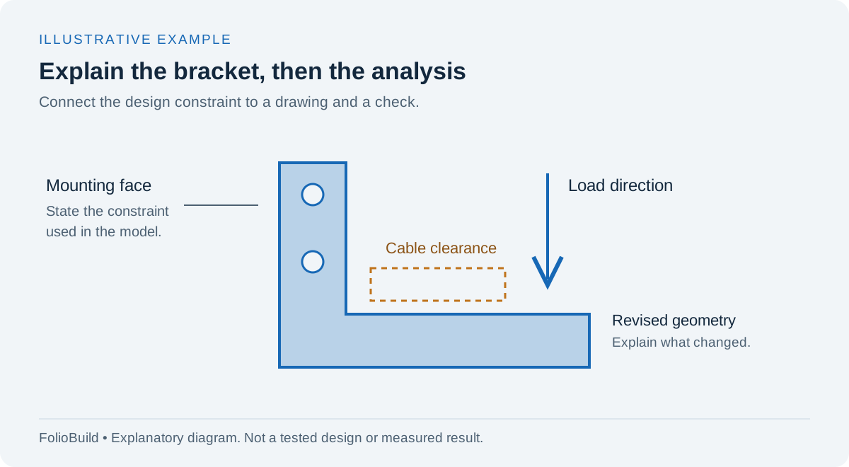
Open the diagram at full size.
An explanation diagram can show the design question before a reader opens a detailed drawing. Label the load, the mounting assumptions and the clearance you are trying to preserve.
Write a short brief with the requirements you actually received. Include dimensions, load cases or limits only when you know them. A missing value is a question to resolve, not a space for AI to fill.
| Part of the brief | What to record |
|---|---|
| Function | What the bracket supports and where it attaches |
| Constraints | Available space, cable access, material and manufacturing process |
| Your role | Which design, analysis and test tasks you personally completed |
| Evidence | Drawing revision, calculation, simulation setup or test record |
| Open question | A requirement or check that remains unresolved |
Show a drawing that explains a choice
Pick a view where the important feature is visible. For the bracket, that might be a side view showing the cable clearance and mounting face. A caption can explain why you moved a hole, changed a bend or added a radius. Save decorative renders for after the reader understands the part.
If you include a drawing, make the relevant dimensions readable on a phone or provide a link to a larger version you have permission to share. Crop empty margins, but keep units, revision information and any notes needed to interpret the image. Describe which surfaces matter to assembly rather than listing every CAD command you used.
Explain the FEA setup before the coloured result
A stress plot needs context. State the load case, the material model, what you constrained and what you simplified. Explain whether the analysis concerns static strength, deflection, temperature or another question. Name the software, but spend more space on the assumptions that affect the answer.
For this illustrative bracket, the first model treats the mounting face as fixed. The portfolio should call that an assumption and explain how it differs from the real bolted connection. A bright red region alone does not establish that a part is unsafe, just as a low reported stress does not prove it is ready to manufacture.
Useful evidence might include:
- A readable view of loads and constraints.
- A result with its units and the location being discussed.
- A note on whether the result changed when the mesh was refined.
- A hand calculation or test comparison, with the limits of that comparison.
Only report checks you performed. If you have not run a mesh study or a physical test, say what remains to be checked. Avoid presenting a simulated result as a measured one.
Connect the result to the next design revision
In the sample scenario, an assembly check reveals that the cable needs more room. The student revises the geometry and repeats the relevant analysis. The useful story is the change and its reason, not an invented percentage improvement.
If your real project did produce measurements, show the starting value, the revised value and the conditions under which you compared them. A claim such as “reduced mass” needs the part versions being compared. A test pass needs a stated test and acceptance criterion. If your result is a working prototype or a clearer manufacturing drawing, that is a legitimate outcome too.
A finished case-study description
This is sample wording for the fictional scenario:
I designed the sensor bracket for our team's test rig. I owned the CAD model and the initial static analysis; a teammate designed the rig. I recorded the cable clearance and assembly constraints, then checked the bracket using a simplified fixed mounting face. An assembly review exposed a cable-access problem, so I revised the profile and documented the change. The portfolio includes the revised drawing and analysis assumptions. The bolted connection and physical behaviour still need validation.
The description makes the contribution and limitation explicit. It does not claim a safety factor, weight saving or successful test that the scenario has not established. Your own version can be shorter, with images and captions carrying some of the detail.
Turn your project notes into a page
Use this outline beside your existing evidence:
- The requirement I worked on was…
- I was responsible for…
- The drawing or model shows…
- I chose this approach because…
- My analysis assumed…
- The check I completed showed…
- The next check or limitation is…
For a broader project worksheet, use the guide to building a portfolio without work experience. If you are applying for a placement, the internship guide explains how to choose which project goes first.
Put the evidence into a mechanical portfolio
The mechanical engineering portfolio guide covers the rest of the page. Preview the Mechanical template to see how a drawing and project explanation fit together, then use its template button to start your own draft.
FolioBuild accepts a CV PDF as input and lets you edit project descriptions, images and links. Add the technical evidence yourself and review any AI draft against your records. If an application asks for a PDF portfolio, prepare that document separately: FolioBuild does not currently export a matching portfolio PDF.